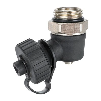
Automating a Straight H Valve involves a series of electrical requirements that are crucial for its proper functioning. As a supplier of Straight H Valves, I understand the importance of these electrical aspects and how they contribute to the overall performance of the automated valve system.
1. Power Supply
The first and most fundamental electrical requirement for an automated Straight H Valve is a suitable power supply. The power supply provides the energy needed to operate the actuator that controls the valve's opening and closing. There are two main types of power supplies commonly used:
1.1 AC Power Supply
Many industrial applications prefer an alternating current (AC) power supply. AC power is readily available in most industrial settings and can provide a stable and reliable source of energy. The standard voltages for AC power supplies used with automated valves are typically 110V or 230V, depending on the region and the specific requirements of the valve actuator.
For example, in North America, 110V AC is commonly used, while in Europe and many other parts of the world, 230V AC is the standard. When selecting an AC power supply for a Straight H Valve, it is essential to ensure that the voltage and frequency match the specifications of the valve actuator.
1.2 DC Power Supply
Direct current (DC) power supplies are also used, especially in applications where a more precise and controlled power source is required. DC power is often used in battery - powered or low - voltage systems. Common DC voltages for valve actuators include 12V, 24V, and 48V.
A 24V DC power supply is a popular choice for many automated valve systems because it offers a good balance between power and safety. It is also compatible with a wide range of control systems and sensors. When using a DC power supply, it is important to consider the current rating, as the actuator may draw a significant amount of current during operation.
2. Actuator Control Signals
The actuator of an automated Straight H Valve needs to receive control signals to operate correctly. These signals determine the position of the valve, whether it is fully open, fully closed, or at an intermediate position.
2.1 Analog Signals
Analog signals are continuous signals that can represent a range of values. In the context of valve control, analog signals are often used to provide a proportional control of the valve position. For example, a 4 - 20 mA signal is a common analog signal used in industrial automation.
A 4 mA signal may represent a fully closed valve, while a 20 mA signal may represent a fully open valve. Intermediate values between 4 mA and 20 mA can be used to position the valve at any point between fully closed and fully open. The actuator of the Straight H Valve must be able to interpret these analog signals accurately to achieve the desired valve position.
2.2 Digital Signals
Digital signals are discrete signals that can have only two states, typically represented as 0 and 1. Digital signals are often used for on - off control of the valve. For example, a 0 signal may indicate that the valve should be closed, while a 1 signal may indicate that the valve should be open.
Digital signals are simple and reliable, and they are commonly used in applications where the valve only needs to be in one of two positions. However, for more precise control, analog signals are usually preferred.
3. Control System Compatibility
The automated Straight H Valve must be compatible with the control system used in the application. The control system can be a simple programmable logic controller (PLC), a distributed control system (DCS), or a more advanced supervisory control and data acquisition (SCADA) system.
3.1 PLC Compatibility
PLCs are widely used in industrial automation for controlling various processes, including valve operation. When integrating a Straight H Valve with a PLC, it is important to ensure that the valve actuator can communicate with the PLC using the appropriate communication protocol.
Common communication protocols used with PLCs include Modbus, Profibus, and Ethernet/IP. The valve actuator should be able to receive control signals from the PLC and send feedback signals back to the PLC to indicate the valve position.
3.2 DCS and SCADA Compatibility
DCS and SCADA systems are more complex control systems that are used for large - scale industrial applications. These systems require a higher level of integration and communication. The Straight H Valve actuator should be able to communicate with the DCS or SCADA system using standard communication protocols and interfaces.
For example, the valve actuator may need to support OPC (OLE for Process Control) technology to exchange data with the DCS or SCADA system. This allows for real - time monitoring and control of the valve position, as well as the collection of diagnostic information.
4. Safety and Protection
Electrical safety is of utmost importance when automating a Straight H Valve. The valve actuator and associated electrical components must be designed to protect against various electrical hazards.
4.1 Overcurrent Protection
Overcurrent protection devices, such as fuses or circuit breakers, should be installed in the power supply circuit of the valve actuator. These devices protect the actuator from damage caused by excessive current, which can occur due to short - circuits or other electrical faults.
4.2 Overvoltage Protection
Overvoltage protection is also necessary to prevent damage to the valve actuator from voltage spikes or surges. Surge protectors or voltage regulators can be used to ensure that the voltage supplied to the actuator remains within the safe operating range.
4.3 Grounding
Proper grounding is essential for electrical safety. The valve actuator and all associated electrical components should be grounded to prevent electrical shock and to protect against electrostatic discharge.
5. Monitoring and Diagnostic Requirements
In addition to the basic electrical requirements for operation, an automated Straight H Valve may also require monitoring and diagnostic capabilities.
5.1 Position Feedback
The valve actuator should provide position feedback to the control system. This allows the control system to verify the actual position of the valve and to detect any discrepancies between the commanded position and the actual position.
Position feedback can be provided using various sensors, such as potentiometers, encoders, or proximity sensors. These sensors convert the mechanical position of the valve into an electrical signal that can be sent to the control system.
5.2 Diagnostic Information
The valve actuator should also be able to provide diagnostic information, such as actuator temperature, motor current, and valve cycle count. This information can be used for predictive maintenance and to detect potential problems before they cause a failure.
Diagnostic information can be communicated to the control system using the same communication protocols used for control signals. This allows for real - time monitoring and analysis of the valve performance.


As a supplier of Straight H Valves, we offer a wide range of products that are designed to meet these electrical requirements. Our valves are compatible with various power supplies, control signals, and control systems, and they are equipped with advanced safety and diagnostic features.
If you are interested in our Straight H Valves or have any questions about the electrical requirements for automation, we encourage you to contact us for further discussion and potential procurement. We also supply Straight Manual Radiator Valve and Straight Automatic Radiator Valve to meet different customer needs.
References
- "Industrial Valve Handbook" by Valve Manufacturers Association
- "Automation and Control Systems" by John Wiley & Sons
- Technical documentation from leading valve actuator manufacturers